
Snappy - Quick Start
Quick Start Guide
Everything from installing the add-on to making a shape, cutting a fit, splitting a model that will not fit the plate, and sending the parts to your slicer.Snappy helps you make printed parts that fit together the first time. It builds shapes from numbers you type. It cuts one shape out of another and leaves a small gap, called a clearance, so the real printed parts fit. It splits a model that is too big for your printer. And it puts the pieces back together afterwards.
Start here
Shaper Pro
Aligner Pro
Cutter
Splitter Pro
When it goes wrong
Getting parts out
Install
Snappy comes as a ZIP file. Download the Free or Pro ZIP and leave it zipped. Blender installs it as it is. There are two ways to install it. Pick either one.
The quick way: drag and drop
- Open Blender.
- Find the ZIP in your file manager (File Explorer on Windows, Finder on a Mac).
- Drag the ZIP onto the Blender window and let go.
- Blender sees that it is an add-on and asks if you want to install it. Confirm. Snappy installs and switches itself on.
The menu way
- In Blender, open the Edit menu at the top of the window and pick Preferences.
- In the window that opens, click Get Extensions on the left.
- Click the small ▾ menu at the top-right of that window.
- Pick Install from Disk… and choose the ZIP.
- To check it worked, click Add-ons on the left. Snappy should be there with its box ticked.
Snappy lives in the sidebar of the 3D viewport. The viewport is the big window in the middle of Blender where your model is. The sidebar is a strip of tabs down the viewport's right-hand edge, and it is hidden until you ask for it. To open Snappy:
- Move your mouse over the 3D viewport.
- Press the N key. The sidebar slides out on the right.
- Click the Snappy Pro tab down the right-hand edge of the sidebar. In Free the tab is called Snappy Free.
If you cannot see the tab, the sidebar is probably still hidden. Put the mouse over the viewport and press N again.
Activating Pro. The first time you open the Snappy Pro tab, it asks for your activation key. It is in your purchase email. Paste it into Activation key and press Activate Snappy. The other panels appear once it is accepted. Free needs no key.
The small "i" buttons. Most panels keep their explanations out of the way. Where you see a small "i", rest the mouse on it to read what that part does. Click it and the same words open in a small window.
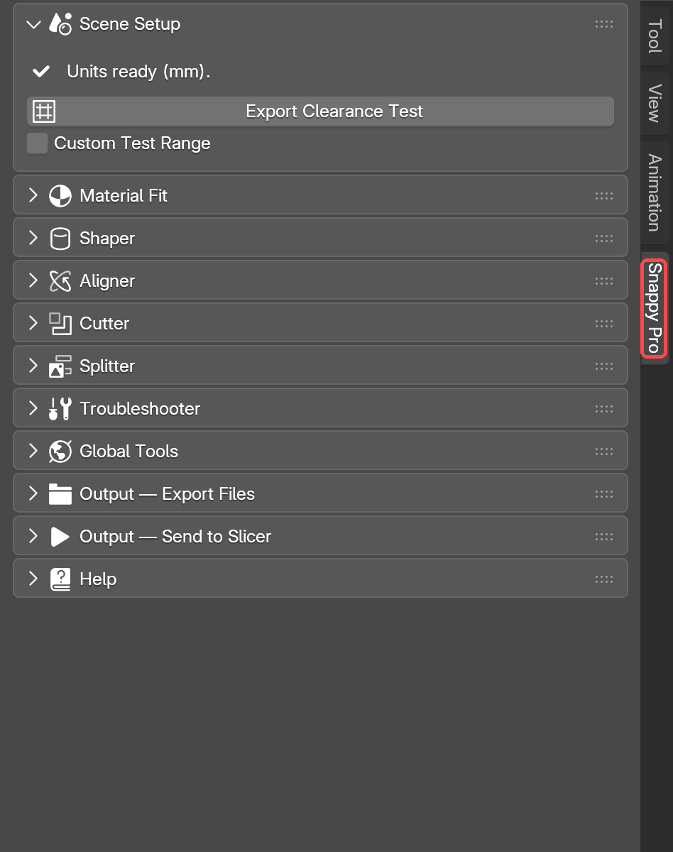
Scene Setup
Snappy measures everything in real millimetres. Blender does not always start that way. If the scene is set to some other unit, a gap you set to 0.2 mm will not come out as 0.2 mm on the printer. Scene Setup fixes this once, so every number after it means what it says.
- Open the Snappy tab. Scene Setup is the first panel.
- Click Prepare Scene Units.
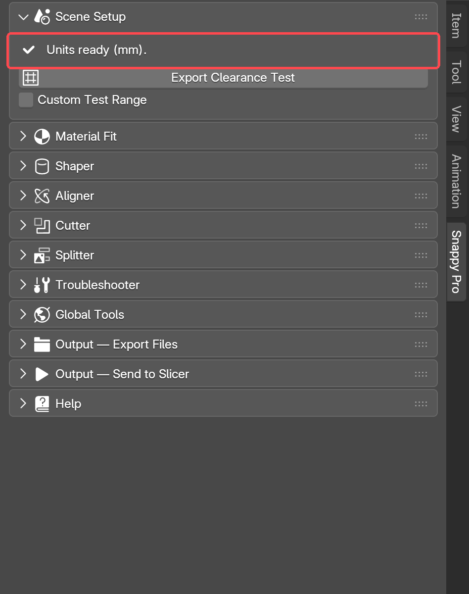
- The panel collapses to a single line reading "Units ready (mm)." That is the sign it worked.
Do this once for every new scene, before anything else. Every other tool in Snappy depends on it.
Two more things stay in this panel after that. Export Clearance Test makes a small test print with several gap sizes in it. Print it with the exact settings you will use for the real part. Then feel which gap slides, snaps or presses the way you want. Use that gap when you cut, and you are not guessing. Custom Test Range Pro sits underneath it. It lets you choose which gap sizes go on the test print, instead of Snappy's own default spread.
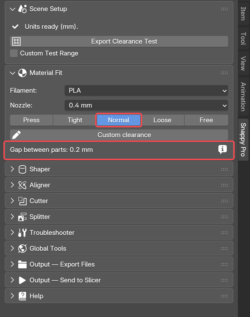
Material Fit
When you cut a hole for a printed part, the hole has to be slightly bigger than the part. That small gap is called the clearance. Without it, the two parts will not go together. Material Fit is where you choose how big that gap is. Every cut you make uses it.
- Pick your Filament, the type of plastic you print with, such as PLA.
- Pick your Nozzle size. 0.4 mm is the usual one.
- Choose a fit: Press, Tight, Normal, Loose or Free. Press is the smallest gap. Free is the largest. The others sit in between.
Start with Normal. Print the parts and try the fit in your hands. If it is too tight, move one step looser. If it is too loose, move one step tighter.
If you would rather type an exact gap, press Custom clearance. A box appears beside it for the number in mm, and the five fit buttons grey out because they are no longer being used. Whichever way you set it, Gap between parts underneath always shows the number Snappy will really cut with.
Press the small "i" beside Gap between parts for the detail. The gap is shared between both sides of the part, so if you measure one edge you should read half of it.
Shaper Pro
Shaper builds a shape from numbers. You do not have to model a box or a cylinder by hand. You type the sizes and Shaper builds it, exactly to the millimetre. It is the quickest way to make a peg, a block, a spacer, or anything else with simple measurements.
- Pick a shape: Box, Cylinder, Tube, Cone or Sphere.
- Type the size in millimetres. Each shape asks for different numbers:
- A Box takes X, Y and Z: its width, depth and height.
- A Cylinder takes a diameter and a height.
- A Tube is a cylinder with a hole down the middle. It takes the same numbers, plus a bore, which is the size of that hole.
- A Cone takes a top diameter as well. Set it to 0 for a sharp point.
- A Sphere just takes a diameter.
- Press New shape. The shape appears in the viewport, at the 3D cursor.
Round shapes also have a Radius & circumference section, folded away under the fields. Open it if a drawing gives you a radius or a distance round the outside. Type into any one and the others follow.
If you select an object that Shaper did not make, the panel says so. Its numbers will not change that object.
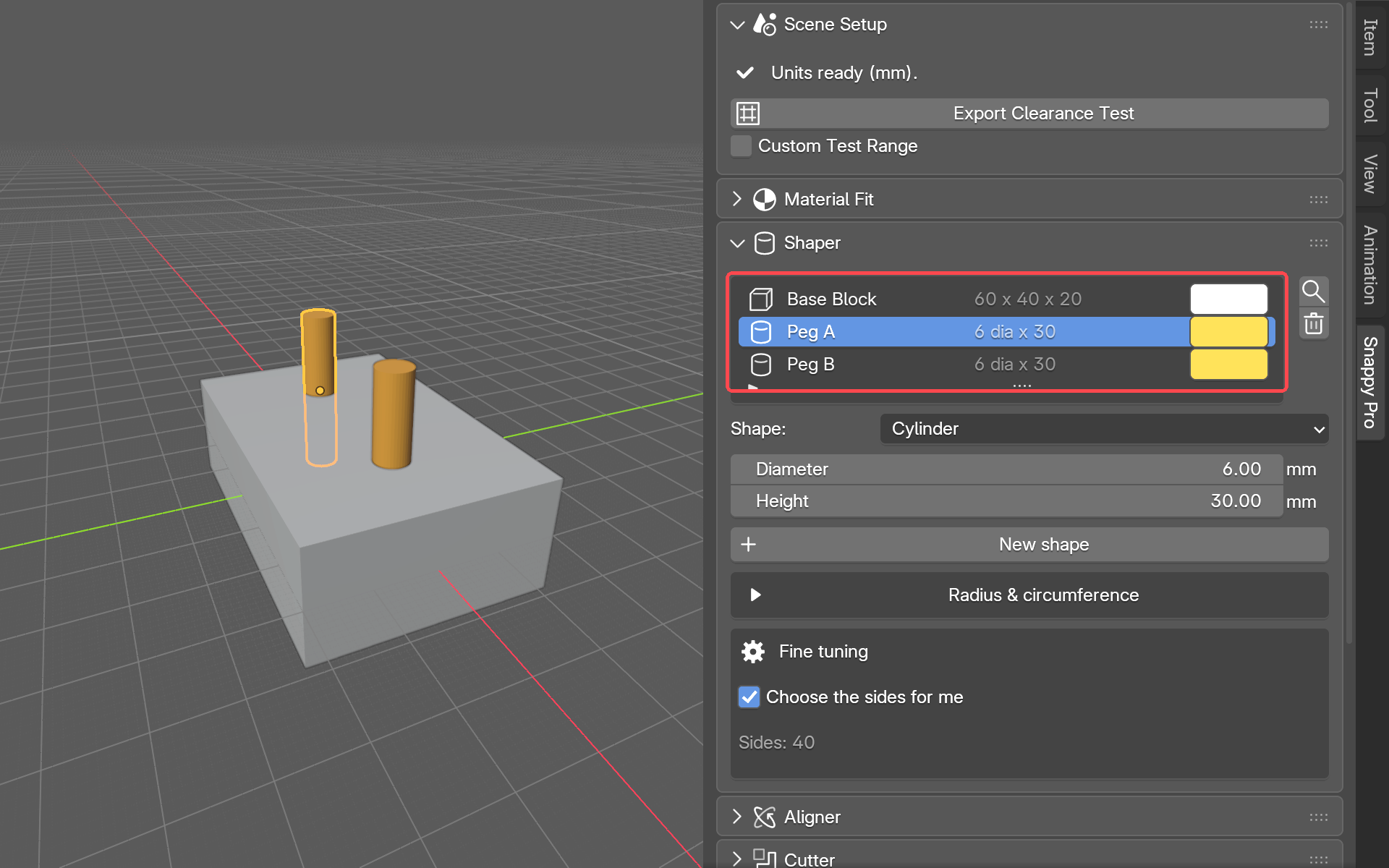
The numbers stay connected to the shape. Change a field and the selected shape rebuilds to match, straight away. Every shape you have made is listed at the top of the panel, above the fields. Each row shows the shape's name, its size and its colour. Click the colour to change it. Click a row to pick that shape. The magnifier beside the list (Go to shape) moves the view to it, and the bin deletes it.
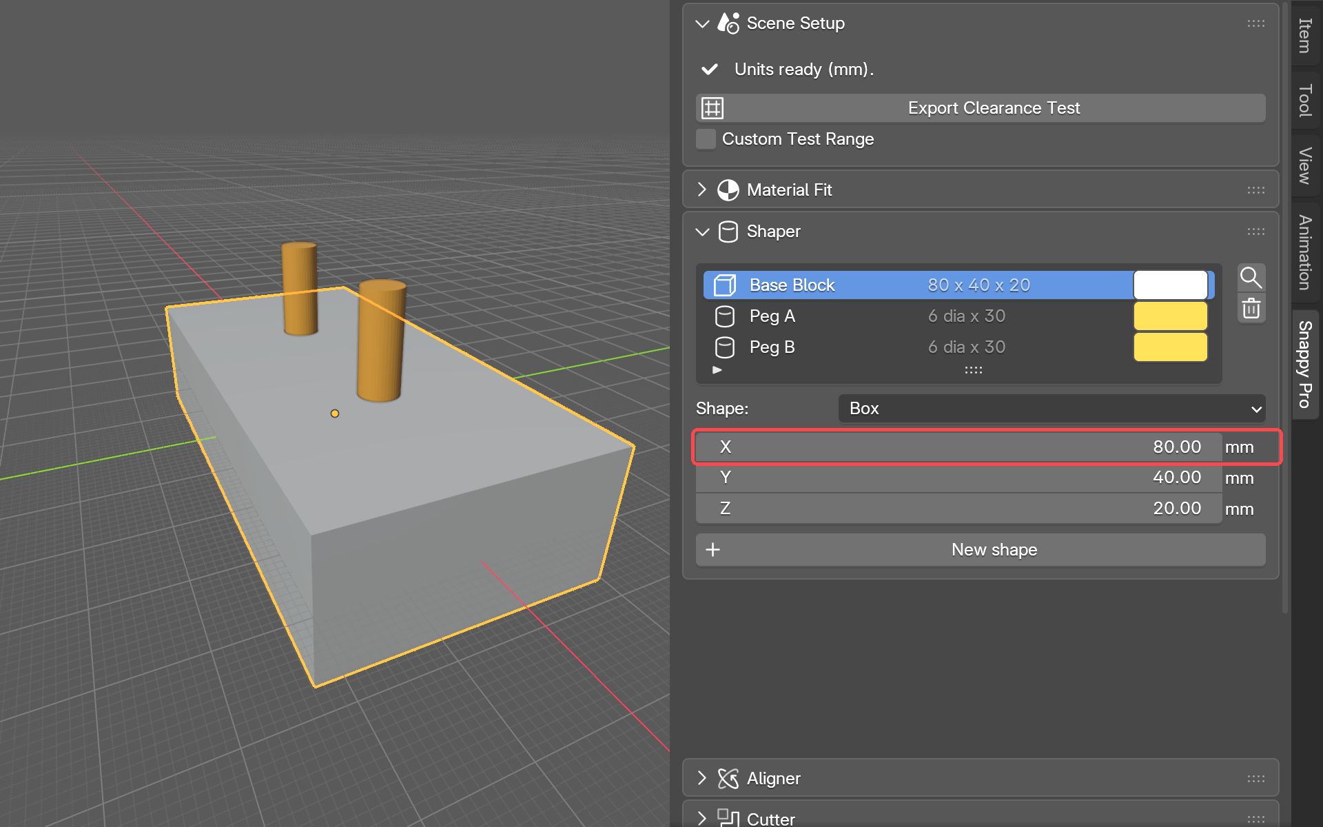
A round shape in Blender is really made of many small flat sides. More sides look smoother. Fine tuning is where you control that. It starts with Choose the sides for me ticked, and a Sides readout below it shows the number Snappy picked. Untick it to set the number of sides yourself, from 3 to 256. If the number is too low for the size, a note tells you how far the corners stick out. The size fields have a limit of their own: dragging stops at 1000 mm, but you can type any size.
Shaper remembers the numbers you typed as a recipe for the shape. Two things can make the shape and the recipe disagree:
- You scaled the shape by hand in the viewport. Snappy writes the new size into the numbers for you. If you stretched a round shape more one way than the other, it cannot, and the panel says "This object's scale is not 1". Press Apply scale to set it straight.
- You edited the mesh itself (the model's surface, made of many small flat faces joined edge to edge), for example by moving individual points on it. Shaper marks it Changed by hand. To keep your edits, press Forget the recipe. The mesh stays exactly as it is, and it stops snapping back to the numbers. Rebuild anyway does the opposite: it throws your edits away and builds the shape from its numbers again.
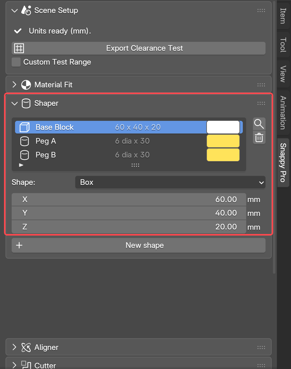
Once a Shaper shape exists, it is a normal Blender object. You can use it as a cutter, split it, or export it straight away.
Aligner Pro
The Aligner moves parts into place for you. It works on any part: a shape you built with Shaper, a piece Snappy cut, a model you downloaded, or one you made yourself. It has two jobs. It puts a part down on the print bed the right way up. And it lines parts up against each other.
Choose your printer and put it on the plate
Snappy needs to know how big your print bed is. Click the Printer heading to open it. It reads "Choose your printer (optional)" until you pick one. Press Preset and type your printer's name, or press Custom and type your own bed size. Show the bed at the part draws the print bed outline around your part, right where the part already is. The part does not move. If a Splitter layout already has printer outlines standing, those are used as the beds. Rest the mouse on the "i" beside the heading to see it say so.
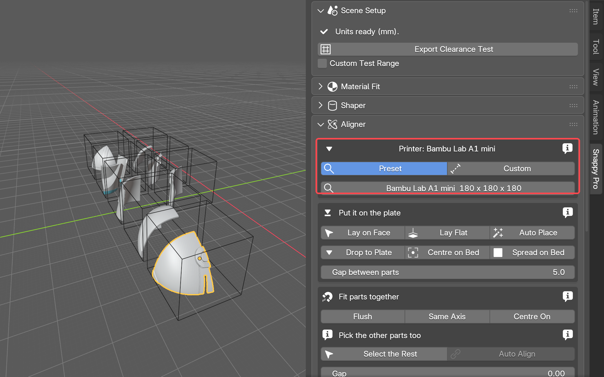
Select a part, then use one of these buttons to put it down on the bed:
- Lay on Face: you click the face you want on the bed, and the part turns so that face is down. A face is one flat surface of a model.
- Lay Flat: puts the part's biggest flat face down. No clicking on the model needed.
- Auto Place: Snappy works out which way up prints best, turns the part that way and sets it on the plate. Once you have chosen a printer, it also centres it on the bed. When two ways up are nearly as good, a Try it button offers the runner-up so you can compare them.
- Drop to Plate: lowers the part straight down until it sits on the bed. It does not turn it.
- Centre on Bed: slides the part to the middle of the plate. It needs a printer chosen. Select several parts and each gets a bed of its own, side by side. If the part has a Splitter printer outline round it, it goes to the middle of that outline.
- Spread on Bed: takes several parts and spaces them out across the plate. The Gap between parts field below the buttons sets how much space is left between them.
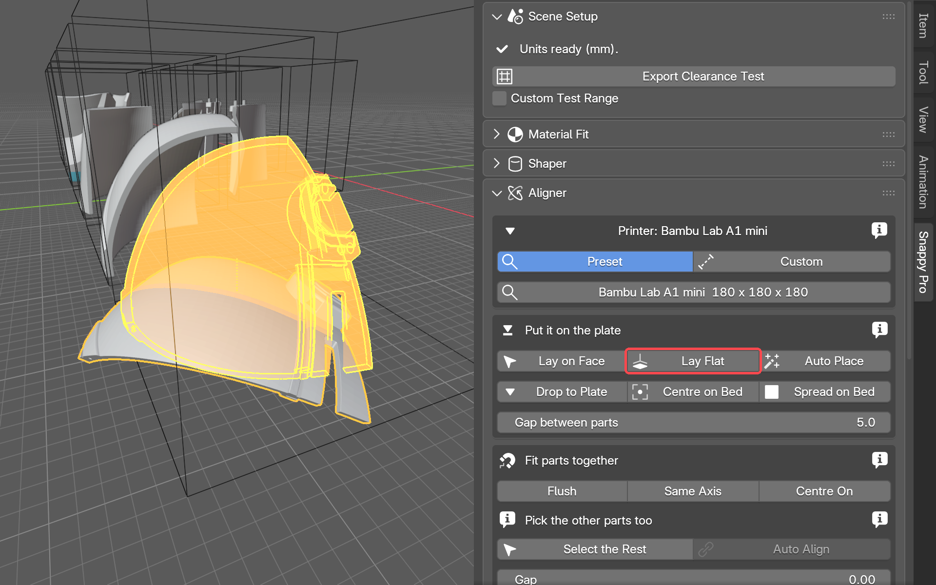
Fit parts together
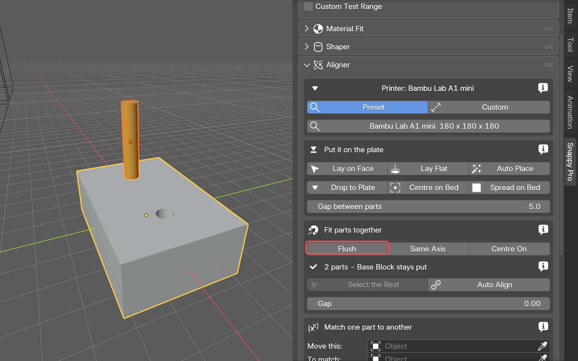
These buttons put one part against another. Each one takes two clicks in the viewport. First, click a face on the part that MOVES. Then click the face on the other part that it should sit against. That second part stays put. The panel tells you which click you are on, and the part you are about to click is outlined in red. Press Esc to cancel.
- Flush: sits the first face flat against the second. The Gap field at the bottom of the box sets any space between them. Leave it at 0 for face to face.
- Same Axis: for round things, such as a peg and a hole. Click the peg or hole on each part, its side or its end, and Snappy lines them up on one centre line.
- Centre On: sits the first face against the second, centred on it.
- Match: copies where one part is, or how it is turned, onto another part. Pick Move this (the part that moves) and To match (the part to copy from). Then choose Rotation, Position, or Both. You can also select the two parts, clicking the one to copy from last, and press Use the selection to fill both fields.
While you use Lay on Face, Flush, Same Axis or Centre On, a see-through copy of the part shows where it will land before you click. After a panel button such as Auto Place or Centre on Bed moves a part, a fading copy shows where it was, with a line to where it went. Switch this off with Show where a part moved from at the bottom of the panel.
Auto Align
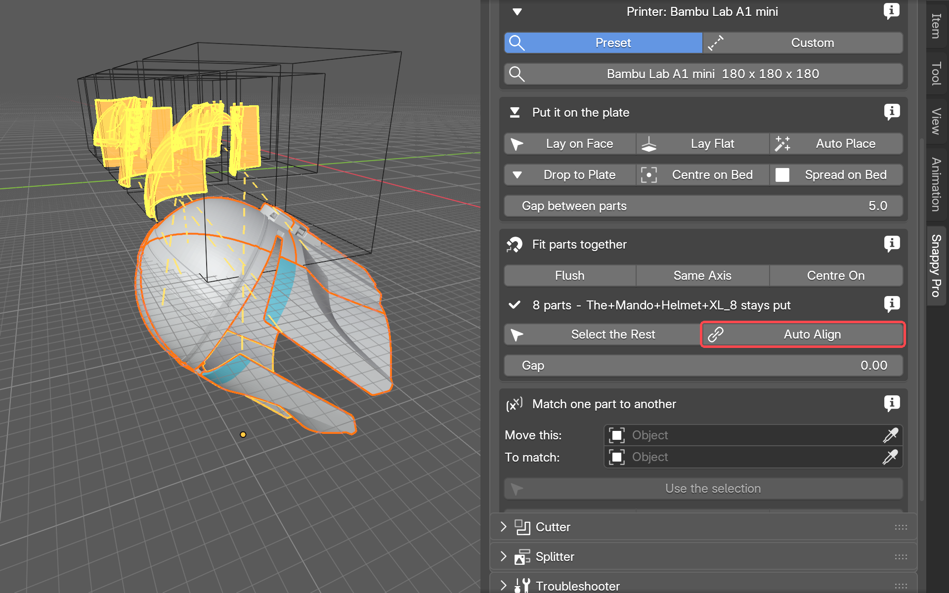
Auto Align puts several parts back together in one go. It is made for pieces the Splitter cut apart, but it works on other parts too.
- Select the parts you want to join. Click the first, then hold Shift and click the others. The part you click last is the one that stays put.
- Press Auto Align.
Above the buttons, one line tells you what Auto Align will do, for example "8 parts - Piece 8 stays put". Rest on its "i" for the whole sentence.
Pieces Snappy cut go back together exactly as they were. Snappy kept a record of where each piece came from, and it lines the connector pins up too. Parts Snappy did not cut are matched by their flat cut faces instead.
Select the Rest saves you some clicking. Select one piece of a Snappy split and press it, and Snappy selects the other pieces from the same split. For parts Snappy did not cut, select them by hand.
Cutter
The Cutter makes a hole in one object, shaped like another object. The object with the hole is the base. The object that shapes the hole is the cutter. Cutting one shape out of another like this is called a Boolean, and you will see that word in the panel. Snappy makes a copy of the cutter that is slightly bigger, by the clearance you chose in Material Fit. Then it takes that copy away from the base. So the hole is a little bigger than the cutter, and the real printed cutter fits into it. The cut stays live. That means you can still move the cutter or change the gap, and the hole follows.
Your first cut
- Make two objects. One is the part you want to cut into, called the base. The other is the shape you want to fit into it, called the cutter. A Shaper shape works well for either.
- Move the cutter so it sits where the hole should be, pushed into the base.
- Open Material Fit. Pick your filament and nozzle size, then choose a fit: Press, Tight, Normal, Loose or Free.
- Open the Cutter panel and click Select Base. Then click your base object in the viewport.
- Click Select Cutter. Then click the cutter object in the viewport. In Pro, if the base already has a cutter, this button reads Add Cutter instead.
That is the whole cut. You do not need to hold Shift and click anything. The hole appears in the base straight away.
Choosing a clearance
Start with Normal. Print both parts and try the fit in your hands. Then move one step tighter or looser. The table shows what each fit gives you, for PLA through a 0.4 mm nozzle:
| Fit | Gap | Good for |
|---|---|---|
| Press | 0.05 mm | A permanent join. It needs force to push together, and then stays put. |
| Tight | 0.10 mm | Goes together by hand, with no wobble. |
| Normal | 0.20 mm | A sliding fit. The recommended starting point. |
| Loose | 0.30 mm | Goes together easily and moves freely. |
| Free | 0.45 mm | Hinges and other parts that need to move. |
You can change the clearance at any time while the cut is live. Do not apply the cut until you are happy with the fit. Applying is permanent (see Applying a cut, below).
Cutting sets Pro
A cutting set is the group of cutters attached to one base object. Snappy keeps them together in one list. A cutter does not have to be a part you will print. It can just be the shape of a hole: a nut trap, a magnet pocket, a bearing seat.
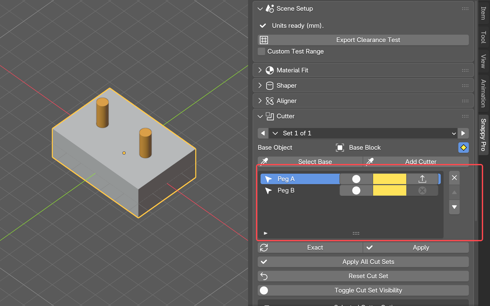
Each row in the list is one cutter. The controls on and below a row do this:
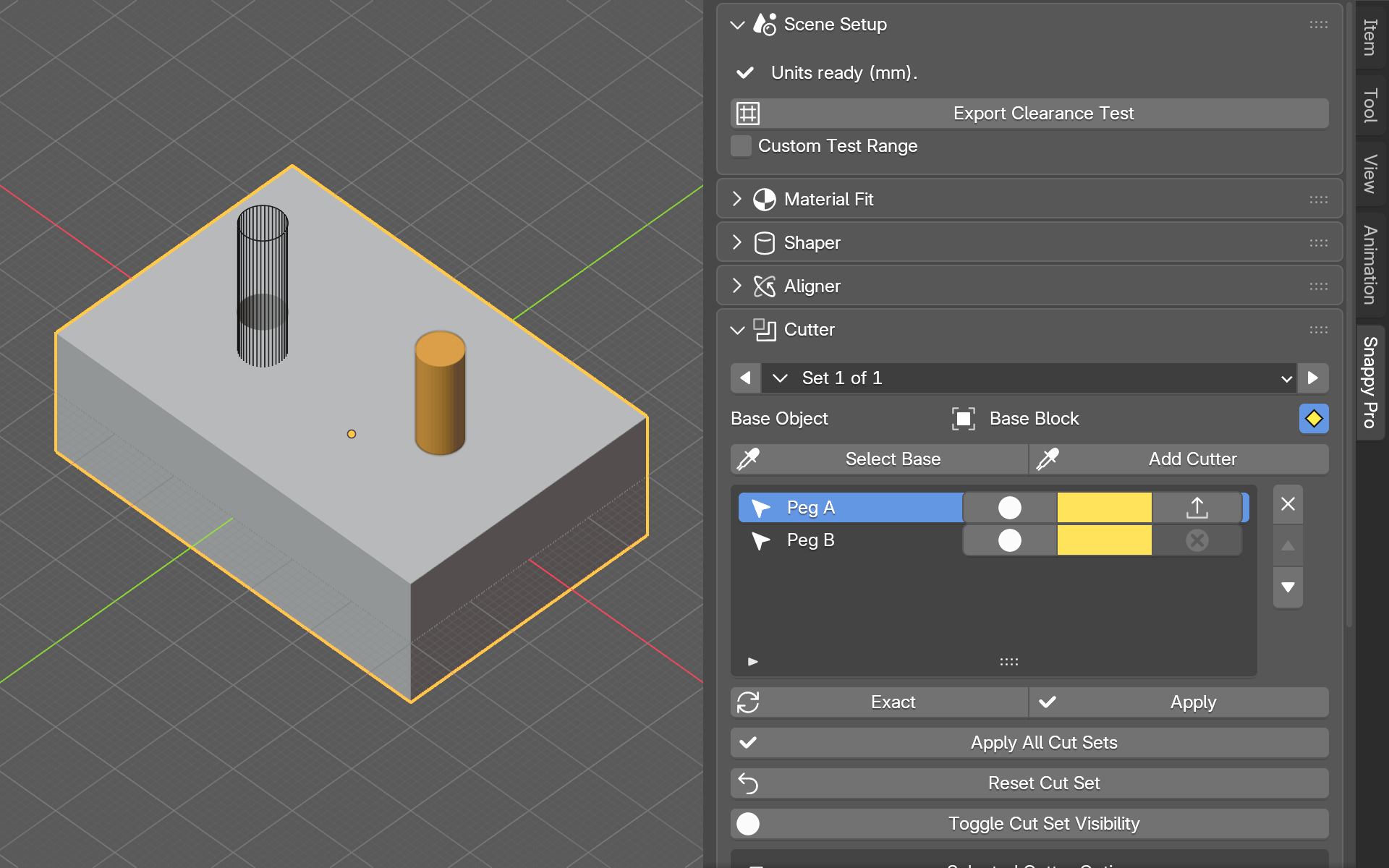
- Visibility: each click steps that cutter through three states: visible, wireframe (see-through, drawn as lines only) and hidden.
- Colour: the colour that cutter is drawn in. Give each cutter its own colour so a busy base stays easy to read.
- Export: whether this cutter's printable part is included when you export. Turn it off for cutters that only make a hole. The arrow icon means the part is in the export; the crossed circle means it is left out. Rest the mouse on it and it tells you which, and what a click will do. It is greyed out on Plain hole cutters, because they never produce a part.
- Solver: the method Blender uses to work out the cut. There is more than one, and sometimes one gives a cleaner result than another. The solver button below the list shows the current solver's name, e.g. Exact. Press it to move the highlighted cutter to the next solver. Try this when a cut looks wrong or leaves small shards behind. It is greyed out on cutters set to Union or Intersect, because the solver is locked while those are on. The panel says so.
Click a row to select that cutter in the viewport. The buttons beside the list (remove, move up and move down) act on the highlighted row. The order matters. Snappy makes the cuts from the top of the list to the bottom. Where two cutters overlap, moving one up or down changes how the cuts combine.

There is one list for each base. The list only shows the cutters that belong to the base you are looking at. To see another base's cutters, use the Set n of n arrows at the top of the panel.
Selected cutter options Pro
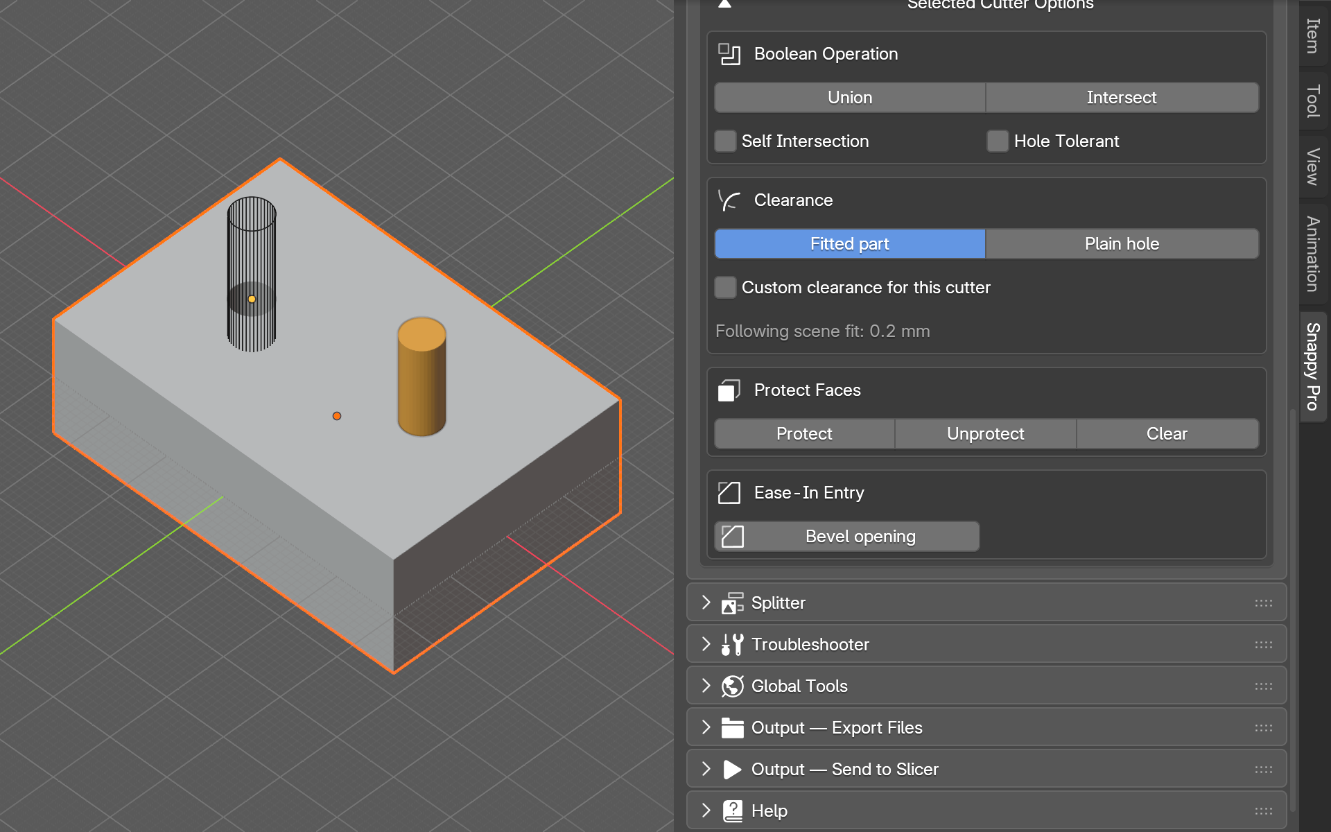
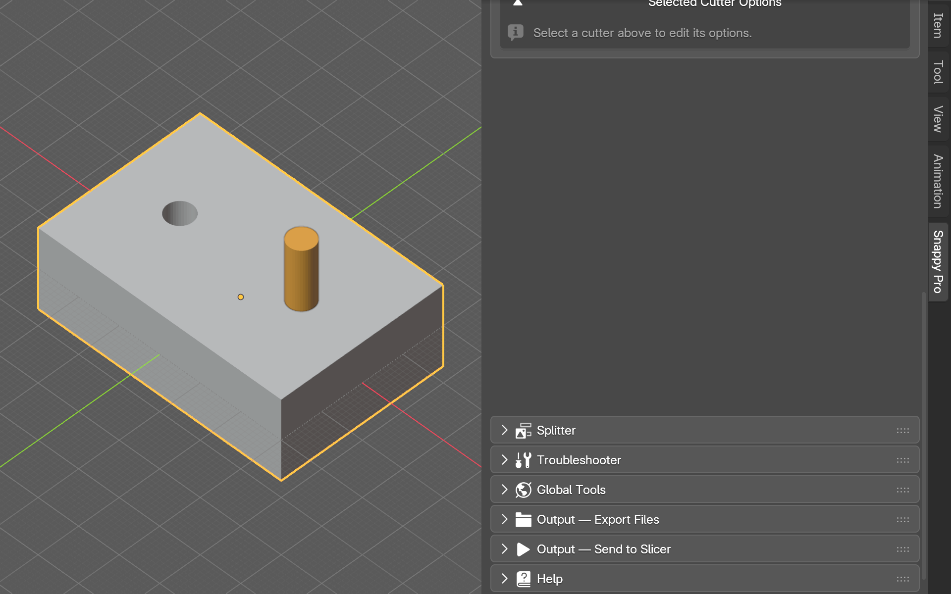
Below the list is a section called Selected Cutter Options. Click it to expand it. Everything in it changes only the highlighted cutter. The other cutters in the set are left alone.
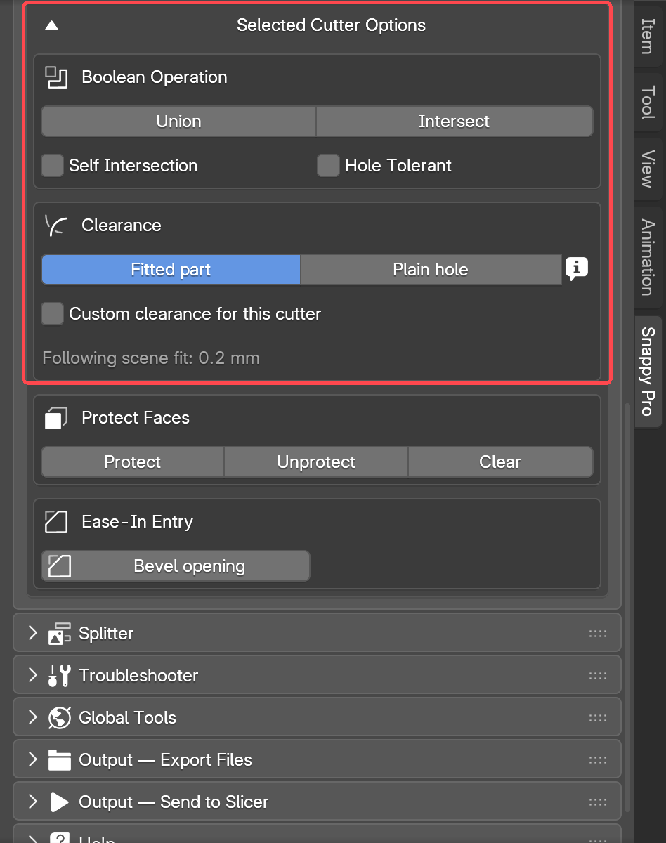
Boolean operation. This is what the cutter does to the base. By default a cutter takes material away. That is the normal cut. There are two other choices. Union adds the cutter's volume onto the base instead of removing it. Intersect keeps only the volume where the two shapes overlap, and removes everything else. With Union and Intersect the clearance has to work the other way round. So Snappy locks the solver for them and greys out its button. The panel explains why: "Solver locked to Exact while using Union." It names whichever solver that cutter had, and Union or Intersect, whichever you picked. To go back to a normal cut, press the lit Union or Intersect button again.
Two tick boxes sit in the same Boolean Operation box. They only appear while the solver is Exact, and they only affect this one cutter. Self Intersection helps when a cutter's surface passes through itself, which can confuse the cut. Hole Tolerant helps when a mesh is not fully closed, meaning its surface has gaps in it. You only need them when a cut goes wrong.
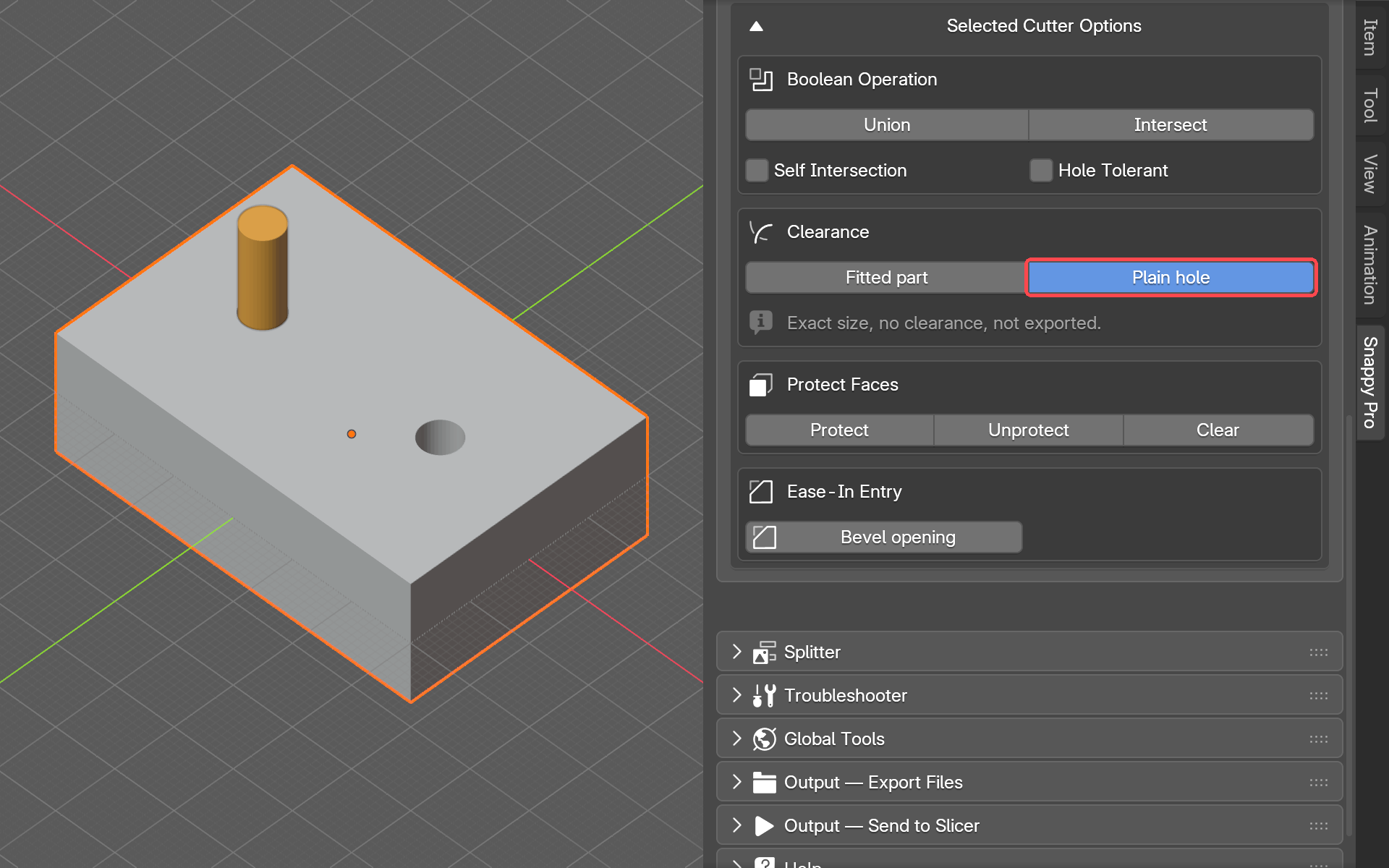
Clearance: fitted part or plain hole. Fitted part is the default. The hole comes out slightly bigger than the cutter, by the fit you chose in Material Fit, or by the custom clearance below. Plain hole adds no clearance at all. The hole is the cutter's exact size. Use it for a hole that will never take a printed part, such as a bolt hole or a pocket for a metal insert.
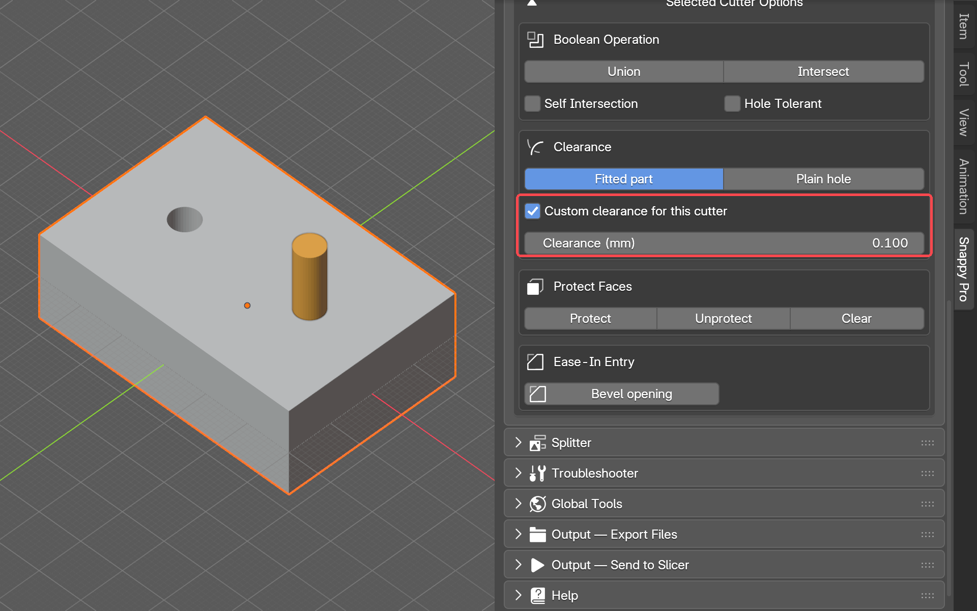
A different clearance for every cutter. Tick Custom clearance for this cutter and type a gap. That cutter then stops following the fit you chose in Material Fit. This lets one model have a press-fit peg at 0.05 mm and a nut trap at 0.15 mm side by side. Cutters without the tick keep following the Material Fit preset. Changing the preset later leaves your custom cutters alone. Without the tick, a greyed line shows what the cutter is following, for example "Following scene fit: 0.2 mm".
Protect Faces. Sometimes one side of a part must sit hard against the hole, with no gap, such as a lid that has to finish flush with the top. Select the cutter, press Tab for Edit Mode, and select the faces that must sit flush (press 3 for faces, click one, hold Shift for more). Press Protect. Those faces turn red and get no clearance, and the gap they would have had goes to the opposite side instead. Unprotect removes the mark from the selected faces. Clear removes every protected face on this cutter. Press Tab again to leave Edit Mode.
Ease-In Entry. On a tight or press fit, the hardest part is getting the first millimetre in. The part catches on the top edge of the hole. Press Bevel opening and Snappy cuts a small slope, called a chamfer, around the mouth of the hole. The part finds its way in instead of catching. Lead-in (mm) sets how big that slope is. It is not only for square or rectangular holes. The slope follows the shape of whatever cutter you used, so round, hex, slotted and irregular openings all get one.
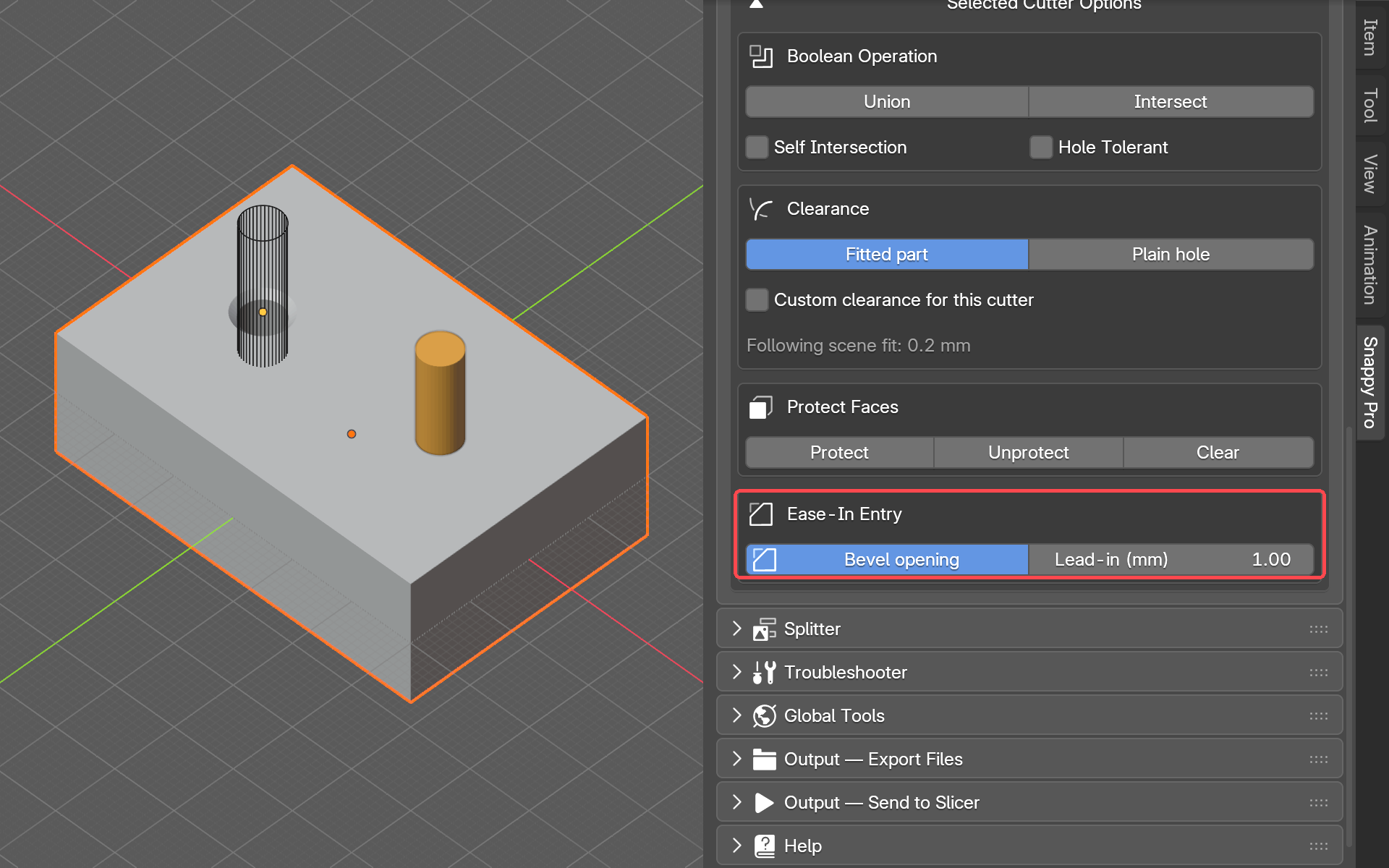
Showing and hiding a cutter. Click Visibility on the cutter's row to step it through visible, wireframe and hidden. Wireframe draws the cutter as lines only, so you can see through it. That is useful while you are placing a cutter: you can see the hole it is making through the shape that is making it. Hidden takes the cutter out of view entirely, once you are happy with the cut. The hole stays either way.
Applying a cut
A live cut can still be changed. Applying a cut makes it permanent. Snappy bakes the hole into the base for good and deletes that cutter, the slightly bigger copy Snappy drew around it, and the part it would have exported. If you still need any of those, export them first.
Most of the time you never need to apply at all. Exporting already bakes the hole into the exported file, and leaves your live setup alone. Apply is for when you want to carry on modelling the cut result by hand in Blender.
Apply sits below the list, next to the solver button. It applies the highlighted cutter. Three more buttons sit together at the bottom of the Cutter panel and act on the whole set instead of one cutter: Apply All Cut Sets, Reset Cut Set and Toggle Cut Set Visibility.
Splitter Pro
Some models are bigger than your printer's plate. The Splitter cuts a model like that into pieces that each fit. Where two pieces meet, it adds connectors (small pins or other joiners) so the pieces line back up when you put them together. Then it lays the pieces out across as many plates as they need.
The panel works in four stages, top to bottom: Printer, Seams, Connectors, Split. Start with Printer:
- Select your model. The Splitter's stages appear. (With nothing selected, the panel only says "Select the model you want to split.")
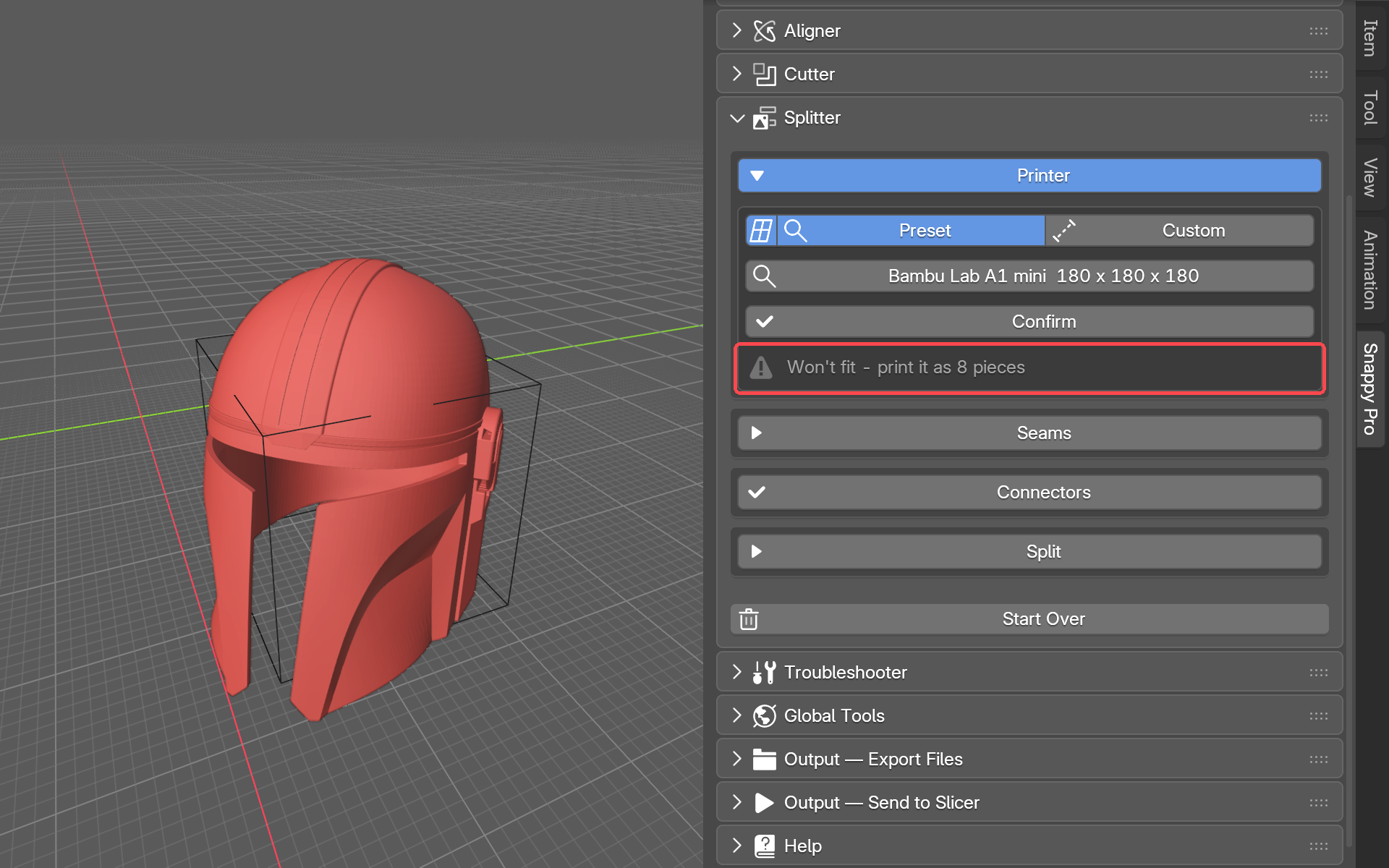
- Open Printer and pick your printer, the same Preset and Custom choice as the Aligner. A build volume outline shows the space your printer can print in. The small grid button at the left switches the outline on or off.
- Straight away the panel says "Fits your printer." or "Won't fit - print it as N pieces", where N is how many pieces it needs. The parts of the model that will not fit are shown red.
- Press Confirm. The printer box folds down to one line. Press that line any time to change the printer or see the fit again.
Auto-Cut
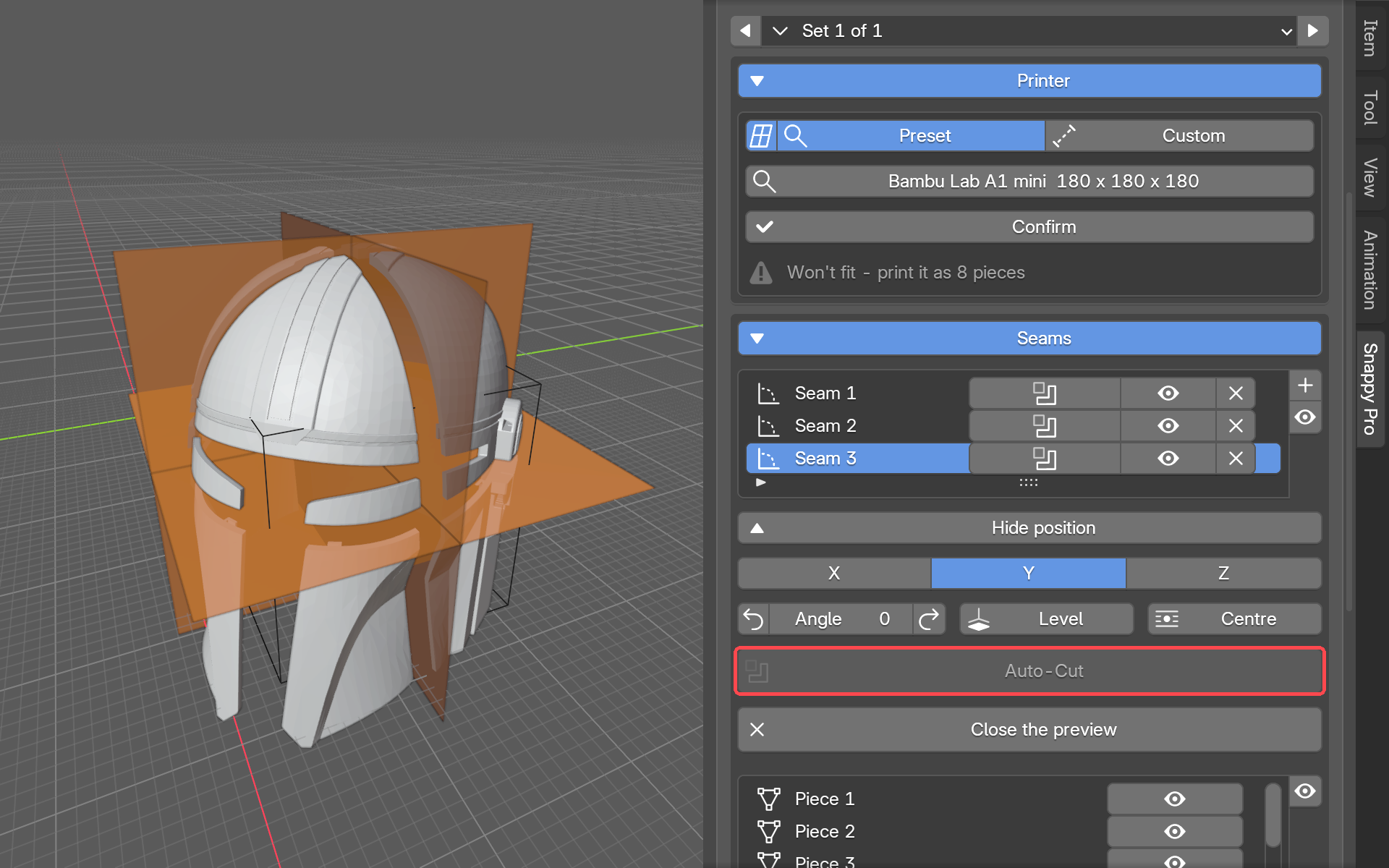
Seams are the lines where the model will be cut. Each seam is shown as a flat sheet, called a plane, passing through the model. Auto-Cut places the seams for you. Open Seams and press Add Split Plane to start. Auto-Cut then appears under the seam list. Press it and Splitter works out how many cuts the model needs and where. It puts a seam at each one, so that every piece will fit the plate, and it replaces any seams you placed yourself. It is greyed out when the model already fits (or before you pick a printer), and after you have used it once. Nudge its seams by hand from there.
Placing seams by hand
You can also place seams yourself, or move the ones Auto-Cut made:
- Press Add Split Plane (or, once there is a seam, the + beside the seam list). A plane appears through the model, ready to move.
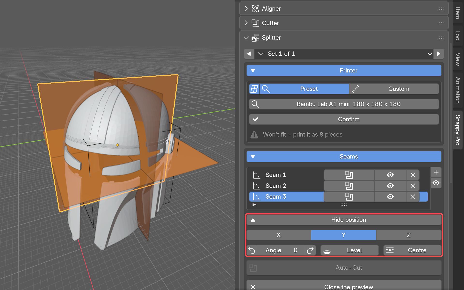
- Click Position this seam. The controls for aiming it open.
- Press Y for a level, flat cut. Press X or Z for an upright cut. X cuts across the model one way, Z the other. Hover a button and Blender tells you which.
- Use Angle to turn it further. The step arrows either side of the number nudge it a little at a time.
- Press Level to put the plane back flat. Press Centre to put it back in the middle of the model.
- Once this seam is where you want it, press + again to add another.
Each seam in the list has an eye icon beside it, which hides that seam. With the mouse over the viewport, the H key does the same thing, and H again brings back what you hid. The X beside a seam removes it. Next to the eye, the cutter-shaped button (Apply Seam) cuts the model at just that seam, straight away. It works with or without a printer. The eye beside the + shows or hides every seam at once. Hide position tucks the aiming controls away once you are done with them.
Preview and connectors
Before you cut for real, you can look at what the split will produce. Press Preview the cut. The pieces ease apart a little, so you can see each one and the joints between them. Nothing has been changed yet. Press Close the preview to put them back together.
You may see some sections coloured blue-teal in the preview. These are small bits a seam sliced off a piece, not pieces in their own right. They print as part of whichever piece they are attached to. They only get connectors as part of that piece's joint, not their own.
While the preview is up, the pieces are listed under the seams: Piece 1, Piece 2 and so on, each with an eye to hide it. A piece too big for the plate reads "Piece 3 - too big" in red. One line under the list tells you what to act on, for example "Fix pieces 2, 5. Click the red or orange parts to see why." If there is only something to know, not fix, it says "Notes on ..." and the "?" beside it has the details.
Click a coloured part to see what is wrong. In the preview, click anything coloured and a small window tells you what is wrong and what to do, often with a button that fixes it. If nothing opens, there is nothing to fix there.
| You see | What it means |
|---|---|
| Amber pin | Thin wall here. Fine if your printer handles thin walls. Buttons: Accept thin walls and Print a Connector Test. |
| Amber pin, “Only 1 of 2 fit on this face” | The joint holds fewer pins than Connectors per Face asked for, and the pop-up says why. One pin still locates the joint. Press Fine, leave them to turn those pins grey, or Smaller connectors. |
| Red pin | Too close to the outside, and it may show through. Drag it further into the part, or press Smaller connectors or Allow X mm walls. |
| Red ghost pin | No connector fits on this joint. Glue these pieces after printing, or press Try dovetails (whole model). |
| Red ball | No dovetail or T-slot fits on this joint: a rail runs along the wall, and here the wall runs across the way the pieces slide together. Glue these pieces after printing, or press Switch to pins (whole model). |
| Blue section | A small bit that prints as part of the piece around it. Nothing to do. |
| Orange section | Not attached to any piece, so it prints loose. Glue it on after printing, or move a seam so it stays on a piece. |
| Red piece | Too big for the plate. Add a seam through it, or press Auto-Cut. |
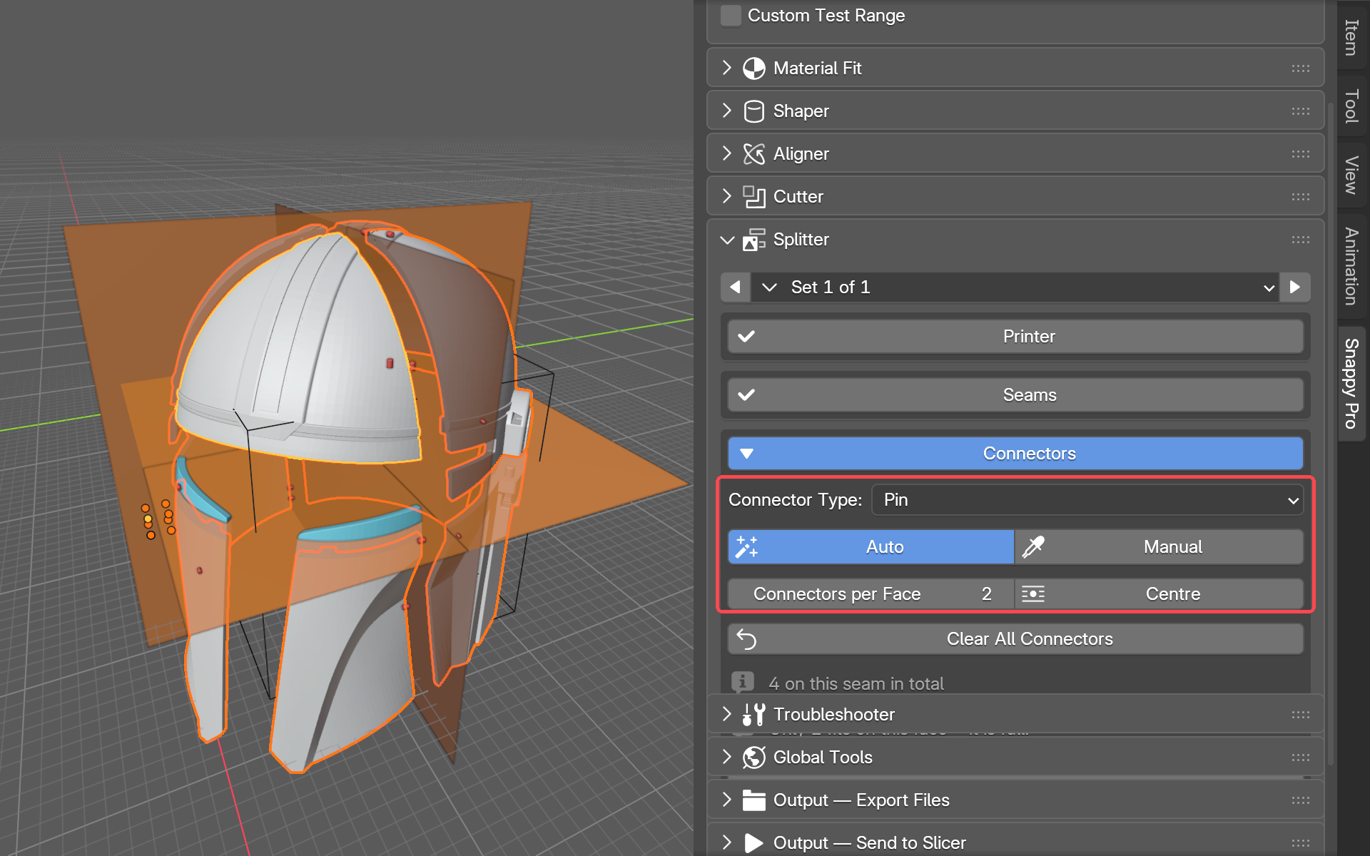
Connectors are the joiners that hold the pieces in line when you put them back together. Set them up in the Connectors stage:
-
Connector Type: pick the kind of joiner: Pin, Tapered Pin, Hex Pin, Dovetail, T-Slot, or Your own shape. Pick None (plain cut) to glue or bolt the pieces with no joiners. These settings apply to every seam on the model.
- Dovetail and T-Slot are sliding joints: one per face, and the panel reminds you "Slides together - needs an open edge." Their fine tuning adds Groove angle, Flare and Extra across / depth.
- Your own shape uses a shape you made in Shaper, such as a magnet or a dowel. Turn on Print the connectors separately and both halves get a pocket for it.
- Auto places the connectors for you. Manual lets you place them yourself. In Manual, move over a cut face: yellow means a connector fits there, red means it does not. Click to place one. Press Esc or right-click when you are done. Once you have started placing by hand, Add More lets you keep adding. The small reset button beside it removes only the ones you placed by hand.
- Connectors per Face sets how many connectors go on each joining face. If fewer fit, the panel says so, for example "Only 2 fit at this size".
- Centre puts a single connector in the middle of the face. It sets the count to 1.
- Clear All Connectors removes every connector, leaving bare seams.
If some pins had to go on thin walls, or some joints got none at all, one line says so, for example "12 of 46 connectors are on thin walls (amber, down to 0.6 mm). 2 joints got no connectors - glue them." Accept thin walls sets Keep off the walls to that thinnest wall, so the amber pins turn grey. Press it once your Connector Test shows your printer can do it. Show bare joints selects and frames the pieces that got no connector.
A red line with a "?" means some pins are closer to the outside than Keep off the walls allows. Click a red pin to see which.
Show fine tuning opens the more detailed settings. You can leave all of these alone for a first split.
- Auto size, Auto length and Auto chamfer: each one either lets Snappy work out the number, or takes a number you type by hand.
- Keep off the walls (mm): how far in from the model's outer surface a connector must stay (2 mm to start). If connectors show through the walls of a print, raise it. Where a wall is too thin for it, Snappy steps it down for that joint alone, but never below Thinnest wall my printer prints (mm), the setting just under it (it is in the add-on preferences too). Those pins are drawn amber. A line under the connector controls says how many. Click an amber pin to see how thin its wall is. Print the Connector Test before trusting a thinner wall.
- Print a Connector Test: sends a small test plate straight to your slicer. It has a row of walls at different thicknesses, to find the smallest Keep off the walls that works for you. It also has a row at different clearances, to find the fit you like. Both are built for the connector type and size you have chosen. The line under the button says exactly what: "Test uses ...". It arrives in your slicer as two files, the plate and the loose pins, with your settings printed on the plate. Pick a dovetail or T-slot and the test has a groove in each block and two loose rails to slide along them. If Snappy cannot find your slicer, pressing the button tells you to choose one in the Send to Slicer panel first.
- Custom clearance: gives this split's connectors their own gap, separate from the fit the rest of the model uses. Sliding joints in particular often want a little more than the default.
Lay Out on Plates and Split
When the seams and connectors are how you want them, it is time to cut for real.
Before you press Split, decide on Print the connectors separately, at the top of the Split stage. Leave it off and the pins are built into each piece, which can need supports. Turn it on and Snappy cuts a socket into both halves and the connectors print as loose pieces, so neither half needs supports. Once the pieces exist it greys out.
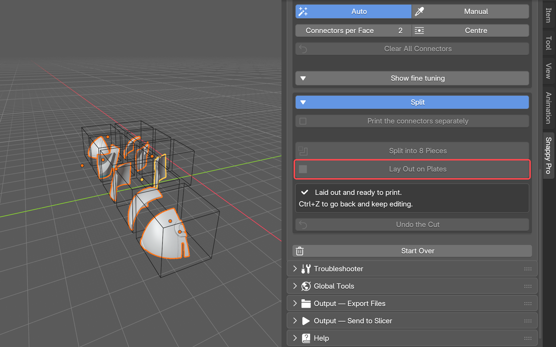
- Press Split at the Seam. With more than one seam, the button reads Split into N Pieces instead. The model is now separate pieces.
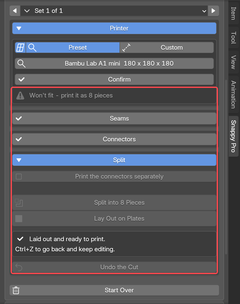
- Press Lay Out on Plates. Snappy arranges the pieces across as many printer outlines as they need, turned to print well and spaced apart, ready to send on. It needs a printer chosen.
To undo the split, press Undo the Cut. It brings the whole model back. Press it before Lay Out on Plates. Once the pieces are laid out, Undo the Cut greys out and Ctrl+Z is the way back, as the panel says.
Start Over throws the split away for the selected model: the seams, the connectors and any pieces. It brings the original model back and puts the fine tuning back to its defaults. With nothing selected, it does this for every model in the project.
Click a stage's heading to open or close it. More than one can be open at once. So Seams can stay open while you work in Connectors, or while you check the fit in Printer (press the printer line to open it again).
The Troubleshooter
The Troubleshooter does two jobs. It keeps heavy models responsive while you work. And it tells you whether a mesh is actually fit to be cut. A mesh is the surface a 3D model is made of: many small flat faces joined edge to edge. If that surface has gaps or tangles in it, cuts can go wrong.
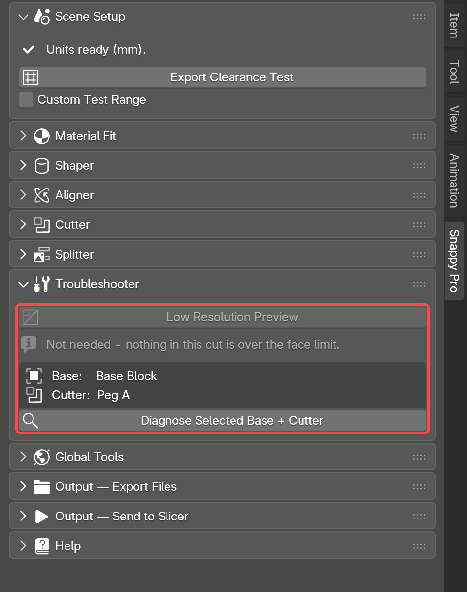
Low Resolution Preview Pro
A very detailed base has many thousands of faces. Cutting it live is slow, and the viewport can stutter while you move a cutter. On a heavy cut, over 50,000 faces in the base or the cutter, Snappy turns on Low Resolution Preview for you and swaps in a lighter stand-in while you drag the cutter, so the viewport keeps up. Untick it if you would rather not, and it stays off for that cut. Live preview face limit appears underneath: lower moves more smoothly, higher looks sharper. On a light cut the button is greyed, and the panel says "Not needed - nothing in this cut is over the face limit."
This stand-in is only for the viewport. Your real geometry, and anything you export, always uses the full-detail mesh.
Diagnose
Most "the cut went weird" problems are really mesh problems. Diagnose checks a pair of objects: one base and one cutter. Right above the button, Snappy names the two it is about to test (Base: Base Block, Cutter: Peg A). Once a pair is picked, press Diagnose Selected Base + Cutter. If you have not picked a pair, select any mesh and the button becomes Check Selected Object, which checks that part on its own. With nothing picked or selected, the panel says "Pick a Base + Cutter above, or select a mesh."
Reading the result
At the top you get a banner: GEOMETRY LOOKS OK or GEOMETRY NEEDS FIXING. Under it is a line for each of the two parts, so you can see which one has the problem. Then comes a recommendation in plain English, telling you what to do about it.
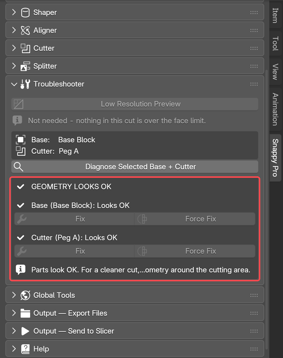
In Pro, Snappy can repair the mesh for you, right there. Fix is the gentle pass. It keeps your shape as it is. Force Fix goes further. It guarantees a watertight mesh, one with no gaps at all, but it can soften sharp edges. Try Fix first, and Force Fix second. Both buttons only light up while a part needs fixing, and each greys out once it has had its go. If both have run and the part still needs work, the panel says "Both repairs tried - Diagnose again to retry". When either one runs, Snappy reports back what it changed.
Mesh repair is new, and still needs work. There are a lot of ways a mesh can be broken, and the fixer will not get every case right yet. If it does not do what you expect, or makes things worse, please report it. Use the Report Issue button in the Help panel. It goes straight to the developer, and every report makes the fixer better for everyone.
Using the tools together
Most of Snappy's tools work on each other's results. A Shaper shape is a normal object once it exists. It can be a cutter or a base. The Splitter can split it. Its pieces go straight to the Aligner and to Export. A model you have split can be cut into again. The Aligner takes anything: a Shaper shape, a piece Snappy cut, a split piece, or something you modelled or downloaded yourself.
In a few places, one tool needs a part to itself. When that happens, Snappy does not just do nothing. It tells you in the panel:
- A base with cutters can be split. The panel warns "the split bakes the cut into the pieces", so the holes come through into every piece. Undo the Cut brings the live cutters back. A cutter will not split, because it shapes the hole. To print a cutter in pieces, press Shift+D to copy it and split the copy.
- A split piece of a Shaper shape still shows the whole shape's numbers. If the piece has connectors, its size is locked, because a resize would lose the pins and the halves would stop fitting. The panel says so and tells you the way: Undo the Cut, resize the whole shape, then split again.
- Splitting a mesh with holes can still run, but the result may not hold up. The Seams stage says "Model has holes - cut may be unreliable." It also makes the preview slow. Run the Troubleshooter and fix the mesh first.
Symptom → fix table
| Symptom | Try |
|---|---|
| Cut looks wrong or leaves shards | Select that cutter in the list. Then press the solver button below the list (it shows the current solver's name, e.g. Exact). Each press tries the next solver. |
| Cutter mesh has problems | Open the Troubleshooter and press Diagnose Selected Base + Cutter. Pro can fix it in place. Free gets a Repair with Formware button for that part. |
| Clearance seems wrong on the print | Check that Scene Setup says "Units ready (mm)." If it does not, press Prepare Scene Units. |
| Viewport is sluggish | Turn on Low Resolution Preview in the Troubleshooter Pro. |
| Want to start over | Reset Cut Set clears the base you are looking at. Reset All Cuts/Splits in Project, in Global Tools, clears everything Pro. |
| The shape won't change from the Shaper panel | A preview may be sitting over it, or the shape itself may be hidden. Close the preview and check both. |
| Auto Align is greyed out | Select two or more parts. The last one you click stays put. |
| Nothing turns red | Choose a printer first. |
| Seam keeps coming back after I hide it | Hide it with the eye icon or the H key, not Alt+H. Alt+H un-hides everything. |
| The connector Centre button is greyed out | Pick a seam and a connector type first. Hover over the button and it tells you which one is missing. |
Global Tools Pro
The buttons in Cutting Sets act on one cutter, or one base. Global Tools acts on the whole project at once. Use it when you are finished adjusting and want to show, hide, apply or reset everything together.
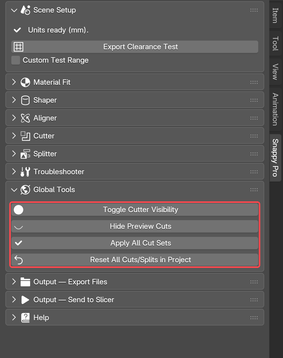
- Toggle Cutter Visibility: shows or hides every cutter in the project in one click.
- Hide Preview Cuts: hides every live cut preview in the project. Nothing is deleted. The button then reads Restore Preview Cuts; press it again to bring them back.
- Apply All Cut Sets: makes every live cut in the whole project permanent at once. It is the same as applying each cutter one by one, and just as permanent.
- Reset All Cuts/Splits in Project: undoes every live cut and split in the project. You are back to the original bases.
Export Files
Exporting writes your parts to files your slicer can open. You do not need to apply a cut first. Snappy bakes the finished shape into the exported file for you, and your live setup in Blender stays as it was.
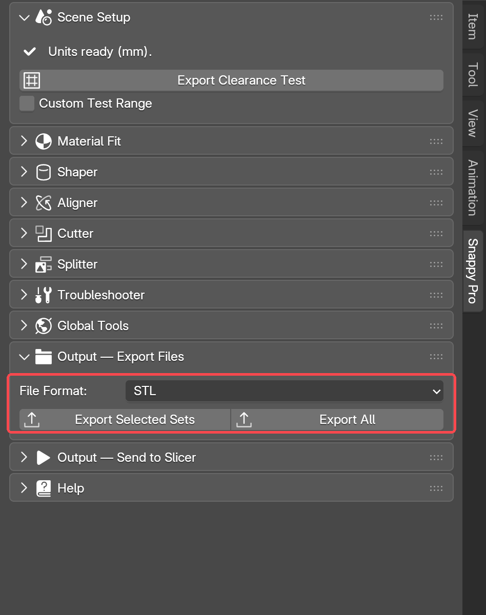
Pick a File Format first. STL is the default, and it is the one you want for printing. 3MF, OBJ and PLY are also there. Then press one of these:
- Export Selected Sets Pro: exports just the bases and printable parts for the cutting sets you have selected.
- Export All: exports everything in the project.
Each exported part has the clearance it was cut at in its file name. A file called Round_Press_Fit_PRINT_ME_0.05mm.stl tells you exactly which test print you are holding when three of them are sitting on the desk. Bases do not get a clearance in their name, because one base can hold several cutters at different clearances.
Where do the files go? Press either button and a file browser opens. Snappy suggests a Snappy_STL_Exports folder next to your saved project (or in your home folder if you have not saved yet). Change it if you like, and type a name if you want one. STL writes one file per part. 3MF writes one file with every part in place.
Send to Slicer Pro
A slicer is the program that turns a model into instructions for your printer. Send to Slicer does the same export as Export Files, then opens the files in your slicer straight away. You do not have to find them in a folder.
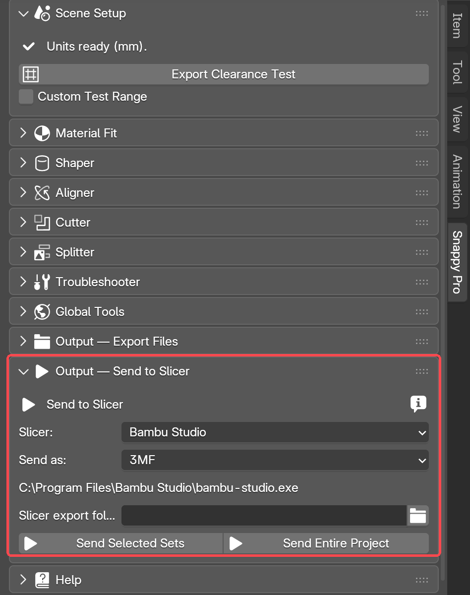
Choose your slicer from the list: Bambu Studio, OrcaSlicer, PrusaSlicer, UltiMaker Cura, Creality Print, AnycubicSlicer, Lychee Slicer, CHITUBOX, or Custom for anything else.
Send as picks the file format for the handoff. It defaults to 3MF. Rest the mouse on the "i" beside the heading and it explains: "Exports one 3MF with every part in place and opens it in your slicer". So you get one file with all the parts in it, instead of the separate file per part that Export Files gives you. Switch Send as to STL and Snappy exports separate STL files instead, one per part, then opens them in your slicer the same way.
Snappy looks for your slicer program on its own. If it finds it, you get a ticked Found: line with the program's path. There is nothing else to do. If it does not find it, the panel says so and gives you a file picker so you can point at the program yourself. You can also set an export folder. Leave it blank to use the default.
- Send Selected Sets: sends only the cutting sets you have selected.
- Send Entire Project: sends everything.
Help and updates
Snappy checks for new versions on its own. When one is ready, a dialog appears the first time you open the Snappy panel. A banner also appears at the top of the panel. Click Install & Restart and Snappy updates itself and reopens your project. The Help panel is where those update controls live, along with this guide and the Report Issue button.
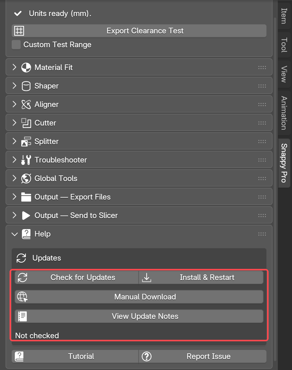
- Check for Updates: asks the LayerLab server whether a newer Snappy is out. The status line underneath tells you what it found.
- Install & Restart: downloads the new version, installs it, then restarts Blender and reopens your project. It only runs on a project that has been saved at least once. If yours has not, it asks you to Save As first. When an update is waiting, you will also see a banner at the top of the Snappy panel.
- Manual Download: lets you fetch the ZIP yourself and install it the way you did the first time. Use it if the in-app installer cannot write to your Blender folder.
- View Update Notes: shows what changed in each release.
- Tutorial: opens this guide.
- Report Issue: tell us what broke, or what you would like next. It goes straight to us.
The update dialog shows what is new, with Install & Restart, Manual Download, Later and a Skip button that names the version. A skipped version stops asking, and Ask Again in the add-on preferences undoes that. The add-on preferences also hold your slicer, Send as, and Thinnest wall my printer prints well (mm).
Free vs Pro
Free gives you the complete fitting workflow. You get clearance-aware cuts, the fit presets, the printable clearance test, mesh diagnosis and export. Free can put more than one cutter in a base, but has no list. Click a cutter in the viewport to work on it. Pro lists them, lets you reorder them, and gives each its own settings.
Pro adds the Shaper and the Splitter, and the rest of the Aligner (Free has Lay on Face and Drop to Plate). It also adds: a list of the cutters on each base, in an order you control; a different clearance for every cutter; a solver, colour and visibility setting for each cutter; Union and Intersect; protected flush faces; Ease-In Entry; mesh repair inside the add-on; Low Resolution Preview; and one-click slicer handoff.